Typology of Bellows Focusing Attachment Model II

Front side type 1
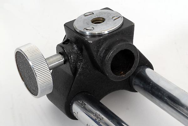
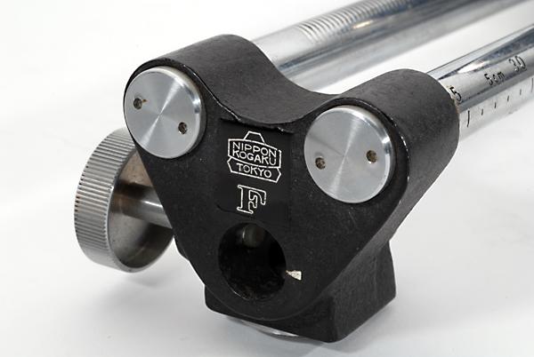
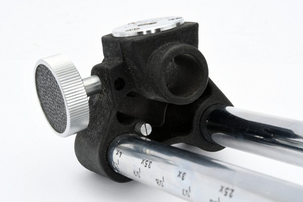
Front side is solid and bears the NKT-logo and Antiqua-F. There is no arrow index on the right side of the socket hole for the slide copy adapter. Chrome tripod mount fixed by three screws. The retainer screw of the slide copy locking knob is in vertical position (bottom side). The maximum extension of the front standard is limited by the end of the gear grooves (no set screw).
Front side type 2
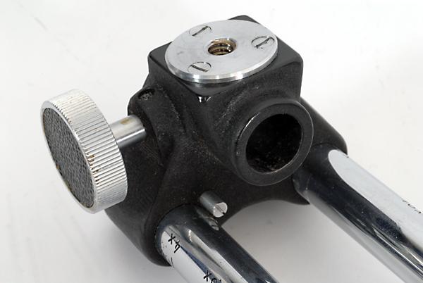
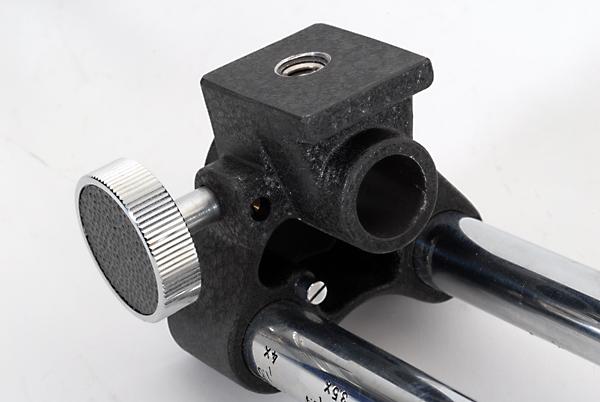
Front side is solid and bears the NKT-logo and Antiqua-F. There is an arrow index on the right side of the socket hole for the slide copy adapter. Chrome tripod mount fixed by three screws. The retainer screw of the slide copy locking knob is in horizontal position (back side). A set screw to limit the maximum extension of the front standard is situated besides the right (grooved) rail.
Front side type 3
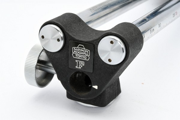
Front side is hollow and bears the NKT-logo and Antiqua-F. There is an arrow index on the right side of the socket hole for the slide copy adapter. Chrome tripod mount fixed by three screws. The retainer screw of the slide copy locking knob is in horizontal position (back side). A set screw to limit the maximum extension of the front standard is situated besides the right (grooved) rail.
Front side type 4
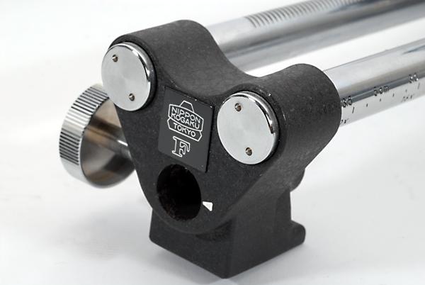
Front side is hollow and bears the NKT-logo and Antiqua-F. There is an arrow index on the right side of the socket hole for the slide copy adapter. The tripod mount is integrated. The retainer screw of the slide copy locking knob is in horizontal position (back side). A set screw to limit the maximum extension of the front standard is situated besides the right (grooved) rail.
Examples: Bellows II 116559
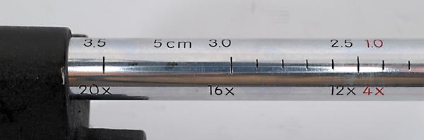
Focusing rails type 1
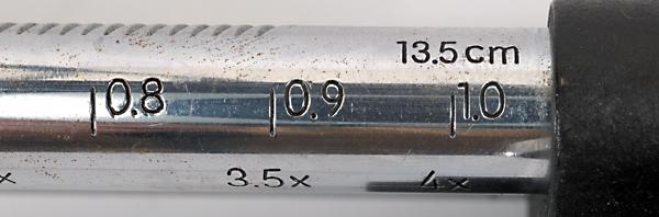
The figures on the chrome focusing rails are large (font size ca. 3 mm).
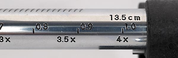
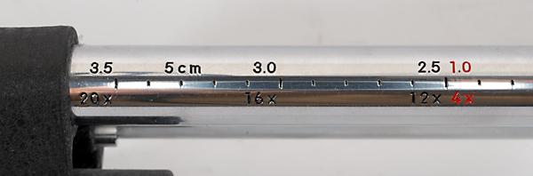
Focusing rails type 2
The figures on the chrome focusing rails are small (font size ca. 2.4 mm).

Rear standard type 1
The rear standard is not compatible with the Photomic finders. Chrome tripod mount fixed by three screws.
Examples: Bellows II 84033, 84082, 84272, 84529, 93222, 1944251

Rear standard type 2
The tube holding the rear bayonet is lengthened by 3 mm to allow the Photomic finders being mounted. The spring catch is partially recessed. The tripod mount is integrated.
Examples: Bellows II 116559

Locking lever set screw type 1
The set screw for the bellows extension lock lever (rear standard) is on the back side.
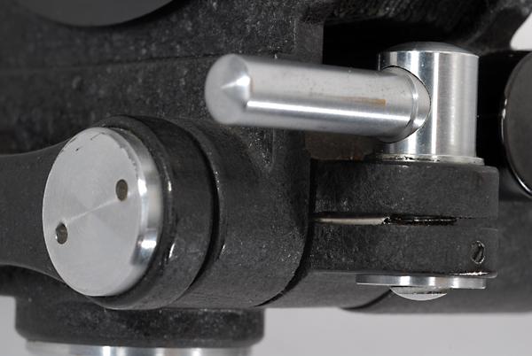
Locking lever set screw type 2
The set screw for the bellows extension lock lever (rear standard) is on the outside.
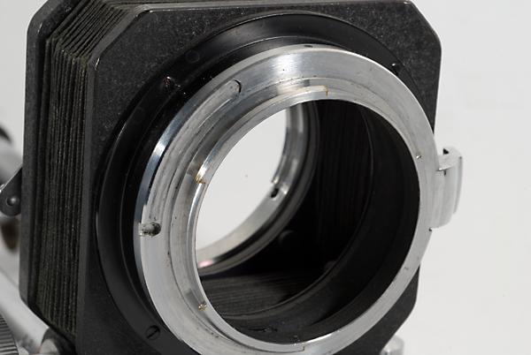
Rear bayonet type 1
There are no screws fixing the rear bayonet. It has an additional shallow groove (from 9 to 11 o'clock position).
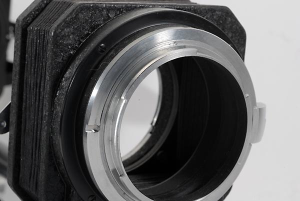
Rear bayonet type 2
There are no screws fixing the rear bayonet. It has no longer the additional groove.
Copyright © Richard de Stoutz 2005 - 2025. All rights reserved.